Product Description
SWP C Type Cardan Shaft(JB/T3241-1991)
Cardan shaft is widely used in rolling mill, punch, straightener, crusher, ship drive, paper making equipment, common machinery, water pump equipment, test bench, and other mechanical applications.
Advantage:
1. Low life-cycle costs and long service life;
2. Increase productivity;
3. Professional and innovative solutions;
4. Reduce carbon dioxide emissions, and environmental protection;
5. High torque capacity even at large deflection angles;
6. Easy to move and run smoothly;
·Mark example:
Tactical diameter D=390mm,Installation length L=1510mm,B type cardan shaft;
SWP390B×1510 Coupling JB/T3241-91
·SWP C Type Cardan Shaft Basic Parameter And Main Dimension(JB/T3241-1991)
| Type | Tactical diameter D mm |
Nominal torque Tn kN·m |
Fatique torque Tf kN·m |
Axis angle β (°) |
Size(mm) | Rotary inertia kg·m2 |
Mass kg |
||||||||
| L | D1 js11 |
D2 H7 |
E | E1 | B×h | h1 | L1 | n-d | |||||||
| SWP160C | 160 | 16 | 8 | ≤10 | 340 | 140 | 95 | 15 | 4 | 20×12 | 6 | 85 | 6-13 | 0.11 | 31 |
| SWP180C | 180 | 20 | 10 | ≤10 | 380 | 155 | 105 | 15 | 4 | 24×14 | 7 | 95 | 6-15 | 0.17 | 42 |
| SWP200C | 200 | 31.5 | 16 | ≤10 | 440 | 175 | 125 | 17 | 5 | 28×16 | 8 | 110 | 8-15 | 0.29 | 59 |
| SWP225C | 225 | 40 | 20 | ≤10 | 520 | 196 | 135 | 20 | 5 | 32×18 | 9 | 130 | 8-17 | 0.51 | 80 |
| SWP250C | 250 | 63 | 31.5 | ≤10 | 540 | 218 | 150 | 25 | 5 | 40×25 | 12.5 | 135 | 8-19 | 0.93 | 119 |
| SWP285C | 285 | 90 | 45 | ≤10 | 600 | 245 | 170 | 27 | 7 | 40×30 | 15 | 150 | 8-21 | 1.88 | 179 |
| SWP315C | 315 | 140 | 63 | ≤10 | 680 | 280 | 185 | 32 | 7 | 40×30 | 15 | 170 | 10-23 | 2.88 | 232 |
| SWP350C | 350 | 180 | 90 | ≤10 | 740 | 310 | 210 | 35 | 8 | 50×32 | 16 | 185 | 10-23 | 4.59 | 300 |
| SWP390C | 390 | 250 | 112 | ≤10 | 820 | 345 | 235 | 40 | 8 | 70×36 | 18 | 205 | 10-25 | 8.64 | 432 |
| SWP435C | 435 | 355 | 160 | ≤10 | 940 | 385 | 255 | 42 | 10 | 80×40 | 20 | 235 | 16-28 | 17.41 | 688 |
| SWP480C | 480 | 450 | 224 | ≤10 | 1060 | 425 | 275 | 47 | 12 | 90×45 | 22.5 | 265 | 16-31 | 28.25 | 904 |
| SWP550C | 550 | 710 | 315 | ≤10 | 1160 | 492 | 320 | 50 | 12 | 100×45 | 22.5 | 290 | 16-31 | 49.25 | 1309 |
| SWP600C | 600 | 1000 | 500 | ≤10 | 1440 | 544 | 380 | 55 | 15 | 90×55 | 27.5 | 360 | 22-34 | 87.17 | 1377 |
| SWP640C | 640 | 1250 | 630 | ≤10 | 1540 | 575 | 385 | 60 | 15 | 100×60 | 30 | 385 | 18-38 | 152.76 | 2635 |
·Product Show
♦Cardan Shaft Types
We can supply you SWP,SWC,WSD,WS universal coupling as following:
Welded shaft type with length compensation / expansion joint
Short type with length compensation / expansion joint
Short type without length compensation / expansion joint
Long type without length compensation / expansion joint
Double flange with length compensation / expansion joint
Long type with big length compensation / big expansion joint
Super Short type with length compensation / expansion joint
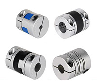
♦Other Products List
| Transmission Machinery Parts Name |
Model |
| Universal Coupling | WS,WSD,WSP |
| Cardan Shaft | SWC,SWP,SWZ |
| Tooth Coupling | CL,CLZ,GCLD,GIICL, GICL,NGCL,GGCL,GCLK |
| Disc Coupling | JMI,JMIJ,JMII,JMIIJ |
| High Flexible Coupling | LM |
| Chain Coupling | GL |
| Jaw Coupling | LT |
| Grid Coupling | JS |
Packaging & Shipping
♦Our Company
HangZhou CHINAMFG Machinery Manufacturing Co., Ltd. is a high-tech enterprise specializing in the design and manufacture of various types of coupling. There are 86 employees in our company, including 2 senior engineers and no fewer than 20 mechanical design and manufacture, heat treatment, welding, and other professionals.
Advanced and reasonable process, complete detection means. Our company actively introduces foreign advanced technology and equipment, on the basis of the condition, we make full use of the advantage and do more research and innovation. Strict to high quality and operate strictly in accordance with the ISO9000 quality certification system standard mode.
Our company supplies different kinds of products. High quality and reasonable price. We stick to the principle of “quality first, service first, continuous improvement and innovation to meet the customers” for the management and “zero defect, zero complaints” as the quality objective.
♦Our Services
1.Design Services
Our design team has experience in cardan shaft relating to product design and development. If you have any needs for your new product or wish to make further improvements, we are here to offer our support.
2.Product Services
raw materials → Cutting → Forging →Rough machining →Shot blasting →Heat treatment →Testing →Fashioning →Cleaning→ Assembly→Packing→Shipping
3.Samples Procedure
We could develop the sample according to your requirement and amend the sample constantly to meet your need.
4.Research & Development
We usually research the new needs of the market and develop the new model when there is new cars in the market.
5.Quality Control
Every step should be special test by Professional Staff according to the standard of ISO9001 and TS16949.
♦FAQ
Q 1: Are you trading company or manufacturer?
A: We are a professional manufacturer specializing in manufacturing
various series of couplings.
Q 2:Can you do OEM?
Yes, we can. We can do OEM & ODM for all the customers with customized artworks of PDF or AI format.
Q 3:How long is your delivery time?
Generally it is 20-30 days if the goods are not in stock. It is according to quantity.
Q 4: Do you provide samples ? Is it free or extra ?
Yes, we could offer the sample but not for free.Actually we have a very good price principle, when you make the bulk order then cost of sample will be deducted.
Q 5: How long is your warranty?
A: Our Warranty is 12 month under normal circumstance.
Q 6: What is the MOQ?
A:Usually our MOQ is 1pcs.
Q 7: Do you have inspection procedures for coupling ?
A:100% self-inspection before packing.
Q 8: Can I have a visit to your factory before the order?
A: Sure,welcome to visit our factory.
Q 9: What’s your payment?
A:1) T/T.
♦Contact Us
Web: huadingcoupling
Add: No.11 HangZhou Road,Chengnan park,HangZhou City,ZheJiang Province,China
/* January 22, 2571 19:08:37 */!function(){function s(e,r){var a,o={};try{e&&e.split(“,”).forEach(function(e,t){e&&(a=e.match(/(.*?):(.*)$/))&&1

Are There Specific Safety Precautions to Consider When Working with Drive Couplings?
Yes, working with drive couplings requires certain safety precautions to ensure the safety of personnel and the integrity of the equipment. Here are some important safety considerations when dealing with drive couplings:
- Lockout-Tagout (LOTO): Before performing any maintenance or repair work on machinery with drive couplings, it is essential to implement a proper lockout-tagout procedure. This involves isolating and securing the power source and equipment to prevent unexpected startup during the maintenance process. Only authorized personnel should have access to the equipment during LOTO procedures.
- PPE (Personal Protective Equipment): Personnel working on or near drive couplings should wear appropriate personal protective equipment, including safety glasses, gloves, and any other required protective gear. This helps protect against potential hazards such as flying debris or pinch points.
- Proper Installation: During installation, it is crucial to follow the manufacturer’s guidelines and instructions to ensure the drive coupling is correctly aligned and mounted. Proper alignment minimizes stresses on the coupling and associated machinery, reducing the risk of premature failure and potential accidents.
- Regular Inspections: Implement a schedule for regular inspections of drive couplings to identify any signs of wear, misalignment, or damage. Addressing issues early can prevent unexpected failures and reduce the risk of accidents or production downtime.
- Load and Speed Limits: Respect the specified load and speed limits of the drive coupling. Exceeding these limits can lead to catastrophic failures and pose safety risks to personnel and equipment.
- Maintenance by Qualified Personnel: Complex maintenance or repair tasks on drive couplings should be performed by qualified personnel with relevant experience and training. Improper maintenance can compromise the coupling’s performance and lead to safety hazards.
- Temperature Limits: Some drive couplings have temperature limits for safe operation. Ensure that the operating temperature is within the recommended range to avoid material degradation and potential hazards.
- Proper Lubrication: If the drive coupling requires lubrication, use the recommended lubricant and apply it as per the manufacturer’s guidelines. Inadequate or excessive lubrication can impact the coupling’s performance and increase the risk of failure.
- Safe Distance: Keep a safe distance from rotating couplings and rotating machinery to prevent accidental contact with moving parts. Implement barriers or guarding to prevent unintentional access.
Adhering to these safety precautions ensures that working with drive couplings is done safely and efficiently, minimizing the risk of accidents and maintaining the longevity of the equipment.
How to Select the Right Drive Coupling for Specific Torque and Speed Requirements
Choosing the appropriate drive coupling for specific torque and speed requirements is essential to ensure reliable and efficient power transmission in mechanical systems. Here are the steps to help you make the right selection:
- Identify Torque and Speed Parameters: Determine the maximum and minimum torque values that the coupling will experience during operation. Also, establish the required operating speed range.
- Consider the Application: Evaluate the application’s characteristics, such as the nature of the driven equipment, the presence of shock loads, vibrations, and misalignments. Different applications may require different coupling types and designs.
- Calculate Service Factor: Apply a service factor to the calculated torque to account for any variations in the load during operation. The service factor typically ranges from 1.2 to 2, depending on the application’s demands.
- Choose the Coupling Type: Based on the torque, speed, and application requirements, select the appropriate coupling type. Common coupling types include elastomeric couplings, grid couplings, gear couplings, and metallic disc couplings.
- Torsional Stiffness and Damping: Consider the desired level of torsional stiffness and damping based on the application’s need for rigidity and vibration absorption. High-speed applications may require couplings with good damping characteristics to prevent resonance.
- Temperature and Environment: Take into account the operating temperature and environmental conditions. Extreme temperatures or corrosive environments may require specific coupling materials or coatings.
- Alignment and Misalignment Tolerance: Assess the alignment capabilities of the coupling. Flexible couplings can accommodate misalignments, while rigid couplings require precise alignment.
- Space Limitations: Consider any spatial constraints for coupling installation. Some couplings may have compact designs suitable for confined spaces.
- Budget and Maintenance: Factor in the initial cost and ongoing maintenance requirements of the coupling. While some couplings may have higher upfront costs, they might offer longer service life and lower maintenance expenses.
- Consult with Manufacturers: Reach out to coupling manufacturers or specialists to discuss your specific requirements. They can provide expert advice and recommend suitable couplings for your application.
By carefully evaluating torque and speed requirements, considering the application’s characteristics, and selecting a coupling that matches the demands of the system, you can ensure optimal performance and longevity of the power transmission setup.

How does a Flexible Drive Coupling differ from a Rigid Drive Coupling?
A drive coupling is a mechanical device used to connect two shafts in a power transmission system. Drive couplings can be broadly classified into two main categories: flexible drive couplings and rigid drive couplings. Each type offers distinct advantages and is suitable for different application requirements. Here’s how a flexible drive coupling differs from a rigid drive coupling:
Flexible Drive Coupling:
A flexible drive coupling is designed with an element that allows some degree of movement and flexibility between the connected shafts. This element can be made of various materials, such as elastomers, metal discs, or grids. The flexibility of the coupling element enables it to accommodate misalignments, shocks, and vibrations, making it ideal for applications where these factors are present.
Main Characteristics:
- Misalignment Absorption: Flexible couplings can compensate for angular, parallel, and axial misalignments between the shafts, reducing stress on connected machinery and extending component life.
- Shock and Vibration Damping: The flexible element of the coupling dampens shocks and vibrations, protecting the connected equipment from sudden impact loads and reducing noise and wear.
- Torsional Flexibility: Flexible couplings can twist and bend, providing torsional flexibility to accommodate fluctuations in torque and prevent damage from torque spikes.
- Energy Absorption: In high-torque applications, the flexible element absorbs energy and reduces peak loads, which can be beneficial for protecting the drivetrain.
Rigid Drive Coupling:
A rigid drive coupling, on the other hand, is designed to provide a direct and rigid connection between the shafts. It has little to no flexibility or movement in the coupling itself. Rigid couplings are typically used when precise shaft alignment is essential, and there is minimal misalignment or vibration in the system.
Main Characteristics:
- Precision Alignment: Rigid couplings ensure precise alignment between the connected shafts, which is critical in applications requiring accurate positioning and minimal shaft deflection.
- No Misalignment Compensation: Unlike flexible couplings, rigid couplings do not compensate for misalignments, so proper alignment during installation is crucial to prevent premature wear or damage to the equipment.
- Torsional Stiffness: Rigid couplings have high torsional stiffness, meaning they efficiently transmit torque with minimal torsional deflection.
- High Torque Capacity: Due to their solid construction, rigid couplings can handle higher torque loads compared to some flexible coupling types.
In summary, the choice between a flexible drive coupling and a rigid drive coupling depends on the specific application’s requirements, including the degree of misalignment, shock and vibration levels, torque capacity, and precision alignment needs. Flexible couplings are suitable for applications with misalignments and dynamic loads, while rigid couplings are preferred for precise positioning and high-torque applications with minimal misalignment.


editor by CX 2024-05-14