Product Description
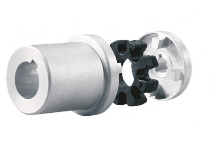
GIICLZ Type Drum Gear Coupling(JB/T 8854.2-2001)
♦Description
GIICLZ drum-shaped gear coupling has the relative offset performance of 2 axes compensated in a certain angle direction and works long distances with the middle axle. It is suitable for connecting horizontal 2 coaxial lines with a certain angular displacement of the transmission shafting.
♦Features
1. Small radial dimension and large bearing capacity are commonly used in shafting transmission under low speed and heavy load conditions.
2. Under the same outer diameter of the inner gear sleeve and the maximum outer diameter of the coupling, the load-carrying capacity of the drum-shaped gear coupling is 15-20% higher than that of the straight-tooth coupling on average.
3. It can compensate for the relative offset of 2 axes at a certain angle and work long distances with the middle axle.
4. It is suitable for connecting horizontal 2 coaxial axes and driving shafting with a certain angle displacement.
♦Main Dimension and Parameter
| Type |
Nominal torque (kN·m) |
Allowable speed (R/min) |
Shaft hole diameter | Shaft hole length | D | D1 | D2 | D3 | C | H | A | B | e | Rotary inertia Kg.m2 |
Weight | ||
| d1 | d2 | Y | J1type | ||||||||||||||
| GIICLZ1 | 0.4 | 4000 | 30 | 35 | 82 | 60 | 103 | 71 | 71 | 50 | 8 | 2 | 18 | 38 | 38 | 0.005 | 4.1 |
| GIICLZ2 | 0.71 | 4000 | 25 | 28 | 62 | 44 | 115 | 83 | 83 | 60 | 8 | 2 | 21 | 44 | 42 | 0.00625 | 4.8 |
| GIICLZ3 | 1.12 | 4000 | 25 | 28 | 62 | 44 | 127 | 95 | 95 | 75 | 8 | 2 | 22 | 45 | 42 | 0.011 | 7.8 |
| GIICLZ4 | 1.8 | 4000 | 63 | 65 | 142 | 107 | 149 | 116 | 116 | 90 | 8 | 2 | 24.5 | 49 | 42 | 0.039 | 16.5 |
| GIICLZ5 | 3.15 | 4000 | 63 | 65 | 142 | 107 | 167 | 134 | 134 | 105 | 10 | 2.5 | 27.5 | 54 | 42 | 0.5175 | 23.1 |
| GIICLZ6 | 5 | 4000 | 80 | 85 | 172 | 132 | 187 | 187 | 187 | 153 | 10 | 2.5 | 28 | 55 | 42 | 0.10425 | 35.4 |
| GIICLZ7 | 7.1 | 3750 | 100 | 105 | 212 | 167 | 204 | 170 | 170 | 140 | 10 | 2.5 | 30 | 59 | 42 | 0.1898 | 54.3 |
| GIICLZ8 | 10 | 3300 | 100 | 110 | 212 | 167 | 230 | 186 | 186 | 155 | 12 | 3 | 33.5 | 71 | 47 | 0.297 | 67.4 |
| GIICLZ9 | 16 | 3000 | 130 | 135 | 252 | 202 | 256 | 222 | 212 | 180 | 12 | 3 | 34.5 | 37 | 47 | 0.575 | 104.4 |
| GIICLZ10 | 22.4 | 2650 | 130 | 145 | 252 | 202 | 287 | 239 | 239 | 200 | 14 | 3.5 | 39 | 82 | 47 | 0.935 | 133.5 |
| GIICLZ11 | 35.5 | 2350 | 160 | 170 | 302 | 242 | 325 | 250 | 250 | 235 | 14 | 3.5 | 40.5 | 85 | 47 | 1.625 | 193 |
| GIICLZ12 | 50 | 2100 | 190 | 200 | 325 | 282 | 362 | 286 | 313 | 270 | 16 | 4.0 | 44.5 | 95 | 49 | 3.093 | 290 |
| GIICLZ13 | 71 | 1850 | 200 | 220 | 352 | 282 | 412 | 322 | 350 | 300 | 18 | 4.5 | 49 | 104 | 49 | 6.34 | 370 |
| GIICLZ14 | 112 | 1650 | 240 | 250 | 470 | 330 | 462 | 420 | 335 | 380 | 22 | 5.5 | 86 | 148 | 63 | 8.6 | 509 |
| GIICLZ15 | 180 | 1500 | 280 | 285 | 470 | 380 | 512 | 470 | 380 | 380 | 22 | 5.5 | 91 | 158 | 63 | 15.575 | 740 |
| GIICLZ16 | 250 | 1300 | 280 | 300 | 470 | 380 | 580 | 522 | 430 | 430 | 28 | 7 | 104.5 | 177 | 67 | 26.35 | 974 |
| GIICLZ17 | 355 | 1200 | 250 | 260 | 410 | 330 | 644 | 582 | 490 | – | 28 | 7 | 99 | 182 | 67 | 38.825 | 1110 |
| GIICLZ18 | 500 | 1050 | 340 | 360 | 550 | 450 | 726 | 658 | 540 | – | 28 | 8 | 111 | 215 | 75 | 49.5 | 1465 |
| GIICLZ19 | 710 | 950 | 340 | 320 | 470 | 380 | 818 | 748 | 630 | – | 32 | 8 | 116 | 220 | 75 | 139.5 | 2457 |
| GIICLZ20 | 1000 | 800 | 480 | 500 | 650 | 540 | 928 | 838 | 720 | – | 32 | 10.5 | 123.5 | 235 | 75 | 277.25 | 3793 |
| GIICLZ21 | 1400 | 750 | 480 | 500 | 650 | 540 | 1571 | 928 | 810 | – | 40 | 11.5 | 127.5 | 245 | 75 | 435 | 4780 |
| GIICLZ22 | 1800 | 650 | 670 | 680 | 900 | 780 | 1134 | 1036 | 915 | – | 40 | 13 | 131 | 255 | 75 | 852.25 | 7540 |
| GIICLZ23 | 2500 | 600 | 670 | 710 | 900 | 780 | 1282 | 1178 | 1030 | – | 50 | 14.5 | 149.5 | 290 | 80 | 1638.75 | 11133 |
| GIICLZ24 | 3550 | 550 | 800 | 850 | 1000 | 880 | 1428 | 1322 | 1175 | – | 50 | 16.5 | 158.5 | 305 | 80 | 2976.25 | 16110 |
| GIICLZ25 | 4500 | 460 | 1000 | 1040 | – | 1100 | 1644 | 1538 | 1390 | – | 50 | 19 | 162.5 | 310 | 80 | 7198.25 | 27797 |
Note:
The moment of inertia and mass are calculated according to and including J1 axial extension.
2. The axle hole size marked “*” in the axle hole diameter column is only applicable to d1 selection.
3. J1 shaft extension series is recommended.
4. The axle hole diameter with brackets is not used in the new design.
♦Packaging & Shipping
Other products
♦Other Products List
| Transmission Machinery Parts Name |
Model |
| Universal Coupling | WS,WSD,WSP |
| Cardan Shaft | SWC,SWP,SWZ |
| Tooth Coupling | CL,CLZ,GCLD,GIICL, GICL,NGCL,GGCL,GCLK |
| Disc Coupling | JMI,JMIJ,JMII,JMIIJ |
| High Flexible Coupling | LM |
| Chain Coupling | GL |
| Jaw Coupling | LT |
| Grid Coupling | JS |
Company Profile
♦Our Company
HangZhou CHINAMFG Machinery Manufacturing Co., Ltd. is a high-tech enterprise specializing in the design and manufacture of various types of coupling. There are 26 employees in our company, including 2 senior engineers and no fewer than 20 mechanical design and manufacture, heat treatment, welding, and other professionals.
Advanced and reasonable process, complete detection means. Our company actively introduces foreign advanced technology and equipment, on the basis of the condition, we make full use of the advantage and do more research and innovation. Strict to high quality and operate strictly in accordance with the ISO9000 quality certification system standard mode.
Our company supplies different kinds of products. High quality and reasonable price. We stick to the principle of “quality first, service first, continuous improvement and innovation to meet the customers” for the management and “zero defect, zero complaints” as the quality objective.
♦Our Services
1. Design Services
Our design team has experience in Cardan shafts relating to product design and development. If you have any needs for your new product or wish to make further improvements, we are here to offer our support.
2. Product Services
Raw materials → Cutting → Forging →Rough machining →Shot blasting →Heat treatment →Testing →Fashioning →Cleaning→ Assembly→ Packing→ Shipping
3. Samples Procedure
We could develop the sample according to your requirement and amend the sample constantly to meet your need.
4. Research & Development
We usually research the new needs of the market and develop the new model when there is new cars in the market.
5. Quality Control
Every step should be a special test by Professional Staff according to the standard of ISO9001 and TS16949.
♦FAQ
Q 1: Are you a trading company or a manufacturer?
A: We are a professional manufacturer specializing in manufacturing various series of couplings.
Q 2: Can you do OEM?
Yes, we can. We can do OEM & ODM for all the customers with customized artworks in PDF or AI format.
Q 3: How long is your delivery time?
Generally, it is 20-30 days if the goods are not in stock. It is according to quantity.
Q 4: Do you provide samples? Is it free or extra?
Yes, we could offer the sample but not for free. Actually, we have a very good price principle, when you make the bulk order the cost of the sample will be deducted.
Q 5: How long is your warranty?
A: Our Warranty is 12 months under normal circumstances.
Q 6: What is the MOQ?
A: Usually our MOQ is 1 pcs.
Q 7: Do you have inspection procedures for coupling?
A: 100% self-inspection before packing.
Q 8: Can I have a visit to your factory before the order?
A: Sure, welcome to visit our factory.
Q 9: What’s your payment?
A: T/T.
♦Contact Us
Web: huadingcoupling
Add: No.11 HangZhou Road,Chengnan park,HangZhou City,ZheJiang Province,China
/* January 22, 2571 19:08:37 */!function(){function s(e,r){var a,o={};try{e&&e.split(“,”).forEach(function(e,t){e&&(a=e.match(/(.*?):(.*)$/))&&1
Can Drive Couplings Handle Reversing Loads and Shock Loads Effectively?
Yes, drive couplings are designed to handle reversing loads and shock loads effectively in various industrial applications. Their ability to accommodate these dynamic loads makes them suitable for many power transmission scenarios. Here’s how drive couplings handle reversing loads and shock loads:
- Reversing Loads: Drive couplings, especially flexible couplings like elastomeric, grid, and gear couplings, can handle reversing loads without difficulty. These couplings have torsional flexibility, which allows them to compensate for angular misalignments and absorb shocks during load reversals. As the direction of the load changes, the coupling flexes and adjusts accordingly, minimizing stress on the connected equipment. This flexibility also reduces the wear and tear on both the coupling and the connected machinery, leading to improved durability and extended service life.
- Shock Loads: Drive couplings are engineered to handle shock loads efficiently. Shock loads are sudden, high-intensity forces that can occur during equipment start-ups, stops, or unexpected changes in operating conditions. Elastomeric couplings are particularly effective in damping these shock loads due to the flexibility of their elastomeric elements. Grid couplings with a spring-like grid structure and gear couplings with rigid teeth also excel at distributing and absorbing shock loads. Even chain couplings, designed with roller chains, can effectively handle shock loads by absorbing the impact through the rollers and chain links.
When selecting a drive coupling for an application that involves reversing loads or shock loads, it’s essential to consider factors such as the magnitude and frequency of the loads, the operating environment, and the specific coupling’s design capabilities. Manufacturers often provide load capacity charts and guidelines to help users select the appropriate coupling for their requirements.
Proper maintenance and regular inspections are also essential to ensure that the coupling remains in good working condition. Monitoring the coupling’s performance and addressing any signs of wear or damage promptly can prevent unexpected failures and enhance the overall reliability of the power transmission system.
Exploring the Use of Elastomeric Materials in Flexible Drive Couplings
Elastomeric materials play a vital role in the design and function of flexible drive couplings. These materials are known for their unique properties, including flexibility, resilience, and damping capabilities, making them well-suited for various power transmission applications. Here are some key aspects of elastomeric materials in flexible drive couplings:
- Flexibility: Elastomeric materials, such as natural rubber and synthetic elastomers like polyurethane and neoprene, exhibit high flexibility. This flexibility allows them to deform under load, accommodating misalignments and absorbing shocks and vibrations during operation. The ability to flex helps prevent undue stress on the connected machinery and ensures a smooth and reliable power transmission.
- Damping: Elastomers possess excellent damping characteristics, which means they can absorb and dissipate energy when subjected to torsional vibrations and dynamic loads. This damping property is crucial in minimizing resonance and preventing harmful vibrations from propagating through the system. Couplings with good damping capabilities offer improved system stability and reduced wear on components.
- Resilience: Resilience refers to the ability of elastomeric materials to return to their original shape after being deformed by torque or misalignment. This property ensures that the coupling remains functional even after experiencing temporary overloads or torsional stresses. The resilience of elastomers contributes to the longevity and reliability of the coupling.
- Easy Installation: Elastomeric couplings are often designed with a simple and compact structure, making them easy to install and maintain. Their flexibility allows for quick assembly and disassembly, which can be advantageous during equipment maintenance and repairs.
- Misalignment Compensation: The high flexibility of elastomeric materials allows the coupling to compensate for both angular and parallel misalignments between shafts. This ability to tolerate misalignments without transmitting excessive loads to connected equipment protects the machinery from premature wear and damage.
- Cost-Effectiveness: Elastomeric couplings are generally more cost-effective compared to other types of couplings with elaborate designs. Their simple construction and use of elastomeric materials make them an economical choice for various industrial applications.
Elastomeric materials offer a compelling combination of mechanical properties that make them highly suitable for flexible drive couplings. When selecting a coupling for a specific application, considering the type and characteristics of the elastomeric material used is crucial to ensure the coupling meets the performance requirements and environmental conditions of the system.
How to Diagnose and Fix Common Problems with Drive Couplings?
Drive couplings, like any mechanical component, can experience issues over time. Diagnosing and fixing these problems promptly is essential to ensure the proper functioning of the power transmission system and prevent further damage. Here’s a step-by-step guide to diagnose and fix common problems with drive couplings:
- Visual Inspection: Start by visually inspecting the drive coupling and surrounding components. Look for signs of wear, cracks, or damage in the coupling’s flexible elements, bolts, and connections.
- Check for Misalignment: Misalignment is a common cause of drive coupling problems. Use alignment tools to check if the shafts connected by the coupling are properly aligned. Misalignment can lead to premature wear and vibration issues.
- Listen for Unusual Noises: Unusual noises like clunking, rattling, or grinding may indicate problems with the drive coupling. Pay attention to any sounds while the vehicle is in motion.
- Inspect for Fluid Leaks: Check for any transmission fluid leaks around the drive coupling area. Fluid leaks can lead to insufficient lubrication and cause further damage.
- Test for Slippage: Slippage can occur if the drive coupling is not securely transmitting power. Perform tests to see if the transmission slips out of gear or has difficulty engaging.
- Monitor Power Loss: If the vehicle experiences power loss or reduced acceleration, it may be due to a faulty drive coupling. Monitor the engine’s performance and power delivery.
- Inspect Bolts and Fasteners: Loose or worn bolts and fasteners can lead to coupling problems. Check and tighten all connections as needed.
- Examine Torsional Flexibility: For flexible drive couplings, assess the torsional flexibility to ensure it can accommodate torque fluctuations and prevent damage from torque spikes.
- Replace Damaged Coupling: If you find any issues with the drive coupling during inspection, replace the damaged coupling with a new one that matches the required specifications.
- Realign Shafts: If misalignment is detected, realign the shafts to the manufacturer’s recommended tolerances. Proper alignment will help prevent future problems.
- Lubricate as Needed: Some drive couplings require periodic lubrication. Ensure that the coupling is adequately lubricated as per the manufacturer’s guidelines.
- Perform Test Runs: After fixing the drive coupling or making adjustments, perform test runs to ensure that the transmission functions smoothly and there are no unusual noises or vibrations.
It’s essential to follow the manufacturer’s guidelines and maintenance schedules for the specific drive coupling used in your vehicle. Regular maintenance and inspections can help identify and address potential problems early, preventing costly repairs and ensuring the longevity of the power transmission system.


editor by CX 2024-03-27