Product Description
Product Description
Hot Selling GL Type Spline Rigid Shaft Couplings Roller Chain Coupling For Industry Machine
FEATURES
Manufactured according to relevant industrial standards
Available in many sizes, ratings, and product types, including flexible shaft couplings and OK couplings
Fabricated from a variety of high-grade steel
BENEFITS
Several surface treatment processes protect against corrosion
Customized products are available
Large couplings withstand very high torque
Flexible shaft couplings compensate for shaft misalignment
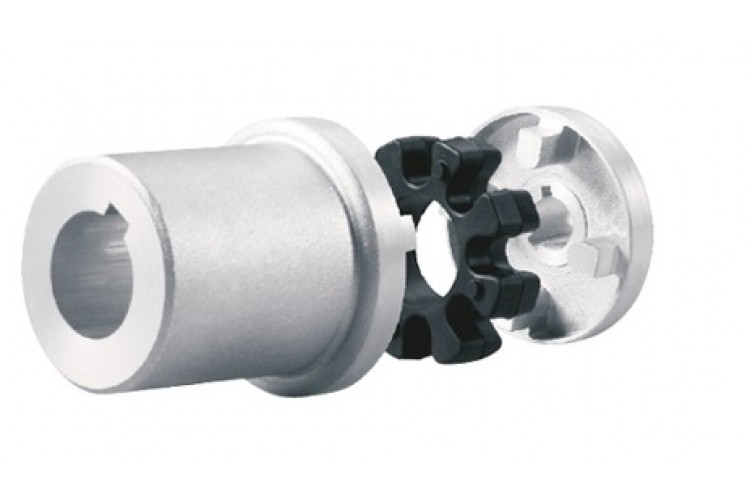
The chain coupling consists of two-strand roller chains, 2 sprockets and AL-Alloy cover, features simple and compact structure, and high flexibility, power transmission capability and durability.
What’s more ,the chain coupling allows simple connection/disconnection, and the use of the housing enhances safety and durability.
The number of roller depends CHINAMFG the specific application
| Chain No. | Pitch
P mm |
Roller diameter d1max mm |
Width between inner plates b1min mm |
Pin diameter d2max mm |
Pin length | Inner plate depth h2max mm |
Plate thickness
Tmax mm |
Tensile strength
Qmin kN/lbf |
Average tensile strength
Q0 |
Weight per meter q kg/m |
|
| Lmax
mm |
Lcmax
mm |
||||||||||
| 08AF36 | 12.700 | 7.95 | 21.70 | 3.96 | 30.8 | 32.1 | 12.00 | 1.50 | 13.8/3135.36 | 16.20 | 1.070 |
| 10AF13 | 15.875 | 10.16 | 16.31 | 5.08 | 27.6 | 29.1 | 15.09 | 2.03 | 22.2/5045 | 27.50 | 1.350 |
| 10AF71 | 15.875 | 10.16 | 19.00 | 5.08 | 30.5 | 32.2 | 15.09 | 2.03 | 21.8/4901 | 24.40 | 1.480 |
| *10AF75 | 15.875 | 10.16 | 45.60 | 5.08 | 57.0 | 58.5 | 15.09 | 2.03 | 21.8/4901 | 24.40 | 2.540 |
| 12AF2 | 19.050 | 11.91 | 19.10 | 5.94 | 32.6 | 34.4 | 18.00 | 2.42 | 31.8/7227 | 38.20 | 1.900 |
| 12AF6 | 19.050 | 11.91 | 18.80 | 5.94 | 31.9 | 33.5 | 18.00 | 2.42 | 31.8/7227 | 38.20 | 1.870 |
| 12AF26 | 19.050 | 11.91 | 19.36 | 5.94 | 31.9 | 33.5 | 18.00 | 2.42 | 31.8/7227 | 38.20 | 1.940 |
| 12AF34 | 19.050 | 11.91 | 19.00 | 5.94 | 31.9 | 31.9 | 18.00 | 2.42 | 31.1/7066 | 38.20 | 1.860 |
| 12AF54 | 19.050 | 11.91 | 19.50 | 5.84 | 31.9 | 31.9 | 18.00 | 2.29 | 31.1/7066 | 38.20 | 1.607 |
| *12AF97 | 19.050 | 11.91 | 35.35 | 5.94 | 48.8 | 50.5 | 18.00 | 2.42 | 31.8/7149 | 38.20 | 2.630 |
| *12AF101 | 19.050 | 11.91 | 37.64 | 5.94 | 51.2 | 52.9 | 18.00 | 2.42 | 31.8/7149 | 38.20 | 1.990 |
| *12AF124 | 19.050 | 11.91 | 20.57 | 5.94 | 33.9 | 35.7 | 18.00 | 2.42 | 31.8/7149 | 38.20 | 1.910 |
| 16AF25 | 25.400 | 15.88 | 25.58 | 7.92 | 42.4 | 43.9 | 24.00 | 3.25 | 56.7/12886 | 63.50 | 3.260 |
| *16AF40 | 25.400 | 15.88 | 70.00 | 7.92 | 87.6 | 91.1 | 24.00 | 3.25 | 56.7/12886 | 63.50 | 5.780 |
| *16AF46 | 25.400 | 15.88 | 36.00 | 7.92 | 53.3 | 56.8 | 24.00 | 3.25 | 56.7/12886 | 63.50 | 3.880 |
| *16AF75 | 25.400 | 15.88 | 56.00 | 7.92 | 73.5 | 76.9 | 24.00 | 3.25 | 56.7/12746 | 63.50 | 5.110 |
| *16AF111 | 25.400 | 15.88 | 45.00 | 7.92 | 62.7 | 65.8 | 24.00 | 3.25 | 56.7/12746 | 63.50 | 4.480 |
| *16AF121 | 25.400 | 15.88 | 73.50 | 7.92 | 91.3 | 94.7 | 24.00 | 3.25 | 56.7/12746 | 63.50 | 6.000 |
*The number of roller depends CHINAMFG the specific application
| Chain No. | Pitch P mm |
Roller diameter d1max mm |
Width between inner plates b1min mm |
Pin diameter d2max mm |
Pin length | Inner plate depth h2max mm |
Plate thickness
Tmax mm |
Tensile strength
Qmin kN/lbf |
Average tensile strength
Q0 kN |
Weight per meter q kg/m |
|
| Lmax
mm |
Lcmax
mm |
||||||||||
| *20AF44 | 31.750 | 19.05 | 32.00 | 9.53 | 53.5 | 57.8 | 30.00 | 4.00 | 86.7/19490 | 99.70 | 4.820 |
| *24AF27 | 38.100 | 22.23 | 75.92 | 11.10 | 101.0 | 105.0 | 35.70 | 4.80 | 124.6/28571 | 143.20 | 9.810 |
| *06BF27 | 9.525 | 6.35 | 18.80 | 3.28 | 26.5 | 28.2 | 8.20 | 1.30 | 9.0/2045 | 9.63 | 0.770 |
| *06BF31 | 9.525 | 6.35 | 16.40 | 3.28 | 23.4 | 24.4 | 8.20 | 1.30 | 9.0/2045 | 9.63 | 0.660 |
| *06BF71 | 9.525 | 6.35 | 16.50 | 3.28 | 24.5 | 25.6 | 8.20 | 1.30 | 9.0/2571 | 9.63 | 0.830 |
| 08BF97 | 12.700 | 8.51 | 15.50 | 4.45 | 24.8 | 26.2 | 11.80 | 1.60 | 18.0/4989.6 | 19.20 | 0.980 |
| *08BF129 | 12.700 | 8.51 | 35.80 | 4.45 | 45.1 | 46.1 | 11.80 | 1.60 | 18.0/4989.6 | 19.02 | 1.500 |
| 10BF21 | 15.875 | 10.16 | 42.83 | 5.08 | 52.7 | 54.1 | 14.70 | 1.70 | 22.0/5000 | 25.30 | 2.260 |
| 10BF43 | 15.875 | 7.03 | 27.80 | 5.08 | 39.0 | 40.6 | 14.70 | 2.03 | 22.4/5090 | 25.76 | 1.140 |
| *10BF43-S | 15.875 | 10.00 | 27.80 | 5.08 | 39.0 | 40.6 | 14.70 | 2.03 | 22.4/5090 | 25.76 | 1.800 |
| *16BF75 | 25.400 | 15.88 | 27.50 | 8.28 | 47.4 | 50.5 | 21.00 | 4.15/3.1 | 60.0/13488 | 66.00 | 3.420 |
| *16BF87 | 25.400 | 15.88 | 35.00 | 8.28 | 54.1 | 55.6 | 21.00 | 4.15/3.1 | 60.0/13488 | 66.00 | 3.840 |
| *16BF114 | 25.400 | 15.88 | 49.90 | 8.28 | 69.0 | 72.0 | 21.00 | 4.15/3.1 | 60.0/13488 | 66.00 | 4.740 |
| *20BF45 | 31.750 | 19.05 | 55.01 | 10.19 | 76.8 | 80.5 | 26.40 | 4.5/3.5 | 95.0/21356 | 104.50 | 6.350 |
| *24BF33 | 38.100 | 25.40 | 73.16 | 14.63 | 101.7 | 106.2 | 33.20 | 6.0/4.8 | 160.0/35968 | 176.00 | 11.840 |
Advantages:
1. Material: C45 steel, Aluminum, Rubber and plastic etc.
2. High efficiency in transmission
3. Finishing: blacken, phosphate-coat, and oxidation.
4. Different models suitable for your different demands
5. Application in wide range of environment.
6. Quick and easy mounting and disassembly.
7. Resistant to oil and electrical insulation.
8. Identical clockwise and anticlockwise rotational characteristics.
9. Small dimension, low weight, high transmitted torque.
10. It has good performance.
| Partnerships Reliable Supply-Chain: |
Based on our experienced team and strict, effective supply chain management, Granville products deliver premium quality, and performance our customers have relied on for years. From a full range of bearings, mounted bearing units, power transmission products, and related markets around the world, we provide the industry’s most comprehensive range of qualified products available today.
Advantage Manufacturing Processesand Quality Control:
01 Heat Treatment
02 Centerless Grinding Machine 11200 (most advanced)
03 Automatic Production Lines for Raceway
04 Automatic Production Lines for Raceway
05 Ultrasonic Cleaning of Rings
06 Automatic Assembly
07 Ultrasonic Cleaning of Bearings
08 Automatic Greasing, Seals Pressing
09 Measurement of Bearing Vibration (Acceleration)
10 Measurement of Bearing Vibration (Speed)
11 Laser Marking
12 Automatic Packing
1 Prevent from damage.
2. As customers’ requirements, in perfect condition.
3. Delivery : As per contract delivery on time
4. Shipping : As per client request. We can accept CIF, Door to Door etc. or client authorized agent we supply all the necessary assistant.
FAQ
Q 1: Are you a trading company or a manufacturer?
A: We are a professional manufacturer specializing in manufacturing various series of couplings.
Q 2:Can you do OEM?
Yes, we can. We can do OEM & ODM for all the customers with customized artworks in PDF or AI format.
Q 3:How long is your delivery time?
Generally, it is 20-30 days if the goods are not in stock. It is according to quantity.
Q 4: How long is your warranty?
A: Our Warranty is 12 months under normal circumstances.
Q 5: Do you have inspection procedures for coupling?
A:100% self-inspection before packing.
Q 6: Can I have a visit to your factory before the order?
A: Sure, welcome to visit our factory.
/* January 22, 2571 19:08:37 */!function(){function s(e,r){var a,o={};try{e&&e.split(“,”).forEach(function(e,t){e&&(a=e.match(/(.*?):(.*)$/))&&1
Can Drive Couplings Handle Reversing Loads and Shock Loads Effectively?
Yes, drive couplings are designed to handle reversing loads and shock loads effectively in various industrial applications. Their ability to accommodate these dynamic loads makes them suitable for many power transmission scenarios. Here’s how drive couplings handle reversing loads and shock loads:
- Reversing Loads: Drive couplings, especially flexible couplings like elastomeric, grid, and gear couplings, can handle reversing loads without difficulty. These couplings have torsional flexibility, which allows them to compensate for angular misalignments and absorb shocks during load reversals. As the direction of the load changes, the coupling flexes and adjusts accordingly, minimizing stress on the connected equipment. This flexibility also reduces the wear and tear on both the coupling and the connected machinery, leading to improved durability and extended service life.
- Shock Loads: Drive couplings are engineered to handle shock loads efficiently. Shock loads are sudden, high-intensity forces that can occur during equipment start-ups, stops, or unexpected changes in operating conditions. Elastomeric couplings are particularly effective in damping these shock loads due to the flexibility of their elastomeric elements. Grid couplings with a spring-like grid structure and gear couplings with rigid teeth also excel at distributing and absorbing shock loads. Even chain couplings, designed with roller chains, can effectively handle shock loads by absorbing the impact through the rollers and chain links.
When selecting a drive coupling for an application that involves reversing loads or shock loads, it’s essential to consider factors such as the magnitude and frequency of the loads, the operating environment, and the specific coupling’s design capabilities. Manufacturers often provide load capacity charts and guidelines to help users select the appropriate coupling for their requirements.
Proper maintenance and regular inspections are also essential to ensure that the coupling remains in good working condition. Monitoring the coupling’s performance and addressing any signs of wear or damage promptly can prevent unexpected failures and enhance the overall reliability of the power transmission system.
Exploring the Use of Elastomeric Materials in Flexible Drive Couplings
Elastomeric materials play a vital role in the design and function of flexible drive couplings. These materials are known for their unique properties, including flexibility, resilience, and damping capabilities, making them well-suited for various power transmission applications. Here are some key aspects of elastomeric materials in flexible drive couplings:
- Flexibility: Elastomeric materials, such as natural rubber and synthetic elastomers like polyurethane and neoprene, exhibit high flexibility. This flexibility allows them to deform under load, accommodating misalignments and absorbing shocks and vibrations during operation. The ability to flex helps prevent undue stress on the connected machinery and ensures a smooth and reliable power transmission.
- Damping: Elastomers possess excellent damping characteristics, which means they can absorb and dissipate energy when subjected to torsional vibrations and dynamic loads. This damping property is crucial in minimizing resonance and preventing harmful vibrations from propagating through the system. Couplings with good damping capabilities offer improved system stability and reduced wear on components.
- Resilience: Resilience refers to the ability of elastomeric materials to return to their original shape after being deformed by torque or misalignment. This property ensures that the coupling remains functional even after experiencing temporary overloads or torsional stresses. The resilience of elastomers contributes to the longevity and reliability of the coupling.
- Easy Installation: Elastomeric couplings are often designed with a simple and compact structure, making them easy to install and maintain. Their flexibility allows for quick assembly and disassembly, which can be advantageous during equipment maintenance and repairs.
- Misalignment Compensation: The high flexibility of elastomeric materials allows the coupling to compensate for both angular and parallel misalignments between shafts. This ability to tolerate misalignments without transmitting excessive loads to connected equipment protects the machinery from premature wear and damage.
- Cost-Effectiveness: Elastomeric couplings are generally more cost-effective compared to other types of couplings with elaborate designs. Their simple construction and use of elastomeric materials make them an economical choice for various industrial applications.
Elastomeric materials offer a compelling combination of mechanical properties that make them highly suitable for flexible drive couplings. When selecting a coupling for a specific application, considering the type and characteristics of the elastomeric material used is crucial to ensure the coupling meets the performance requirements and environmental conditions of the system.

How does a Flexible Drive Coupling differ from a Rigid Drive Coupling?
A drive coupling is a mechanical device used to connect two shafts in a power transmission system. Drive couplings can be broadly classified into two main categories: flexible drive couplings and rigid drive couplings. Each type offers distinct advantages and is suitable for different application requirements. Here’s how a flexible drive coupling differs from a rigid drive coupling:
Flexible Drive Coupling:
A flexible drive coupling is designed with an element that allows some degree of movement and flexibility between the connected shafts. This element can be made of various materials, such as elastomers, metal discs, or grids. The flexibility of the coupling element enables it to accommodate misalignments, shocks, and vibrations, making it ideal for applications where these factors are present.
Main Characteristics:
- Misalignment Absorption: Flexible couplings can compensate for angular, parallel, and axial misalignments between the shafts, reducing stress on connected machinery and extending component life.
- Shock and Vibration Damping: The flexible element of the coupling dampens shocks and vibrations, protecting the connected equipment from sudden impact loads and reducing noise and wear.
- Torsional Flexibility: Flexible couplings can twist and bend, providing torsional flexibility to accommodate fluctuations in torque and prevent damage from torque spikes.
- Energy Absorption: In high-torque applications, the flexible element absorbs energy and reduces peak loads, which can be beneficial for protecting the drivetrain.
Rigid Drive Coupling:
A rigid drive coupling, on the other hand, is designed to provide a direct and rigid connection between the shafts. It has little to no flexibility or movement in the coupling itself. Rigid couplings are typically used when precise shaft alignment is essential, and there is minimal misalignment or vibration in the system.
Main Characteristics:
- Precision Alignment: Rigid couplings ensure precise alignment between the connected shafts, which is critical in applications requiring accurate positioning and minimal shaft deflection.
- No Misalignment Compensation: Unlike flexible couplings, rigid couplings do not compensate for misalignments, so proper alignment during installation is crucial to prevent premature wear or damage to the equipment.
- Torsional Stiffness: Rigid couplings have high torsional stiffness, meaning they efficiently transmit torque with minimal torsional deflection.
- High Torque Capacity: Due to their solid construction, rigid couplings can handle higher torque loads compared to some flexible coupling types.
In summary, the choice between a flexible drive coupling and a rigid drive coupling depends on the specific application’s requirements, including the degree of misalignment, shock and vibration levels, torque capacity, and precision alignment needs. Flexible couplings are suitable for applications with misalignments and dynamic loads, while rigid couplings are preferred for precise positioning and high-torque applications with minimal misalignment.


editor by CX 2024-04-04