Product Description
Stainless Steel Gear Roller Chain Mechanical Power Transmission Drive Parts Components Connection Tyre Grid Jaw Spider Fan Pump Rubber Coupler Manufacturer Round Motor Shaft Price Universal Joint Coupling
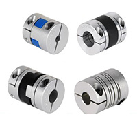
Features
1. Compact designing, easy installation.
2. Convenient maintenance, small size, and lightweight.
3. Absorb the transmission of impact load.
4. Prevent overload.
We can provide the following couplings:
| Rigid coupling | Flange coupling | Oldham coupling |
| Chain Coupling | HRC Coupling | Jaw Coupling |
| Sleeve or muff coupling | Gear coupling | Bellow coupling |
| Split muff coupling | Flexible coupling | Fluid coupling |
| Spacer Coupling | Nm Coupling | MH Coupling |
| Clamp or split-muff or compression coupling | Universal coupling | Variable speed coupling |
| Bushed pin-type coupling | Diaphragm coupling | Constant speed coupling |
Product Description
| SIZE | N.m | r/min |
D | D1 | d1 | L | C | n-M | kg | |
| FCL90 | 4 | 4000 | 90 | 35.5 | 11 | 28 | 3 | 4-M8 | 1.7 | |
| FCL100 | 10 | 4000 | 100 | 40 | 11 | 35.5 | 3 | 4-M10 | 2.3 | |
| FCL112 | 16 | 4000 | 112 | 45 | 13 | 40 | 3 | 4-M10 | 2.8 | |
| FCL125 | 25 | 4000 | 125 | 65 | 50 | 13 | 45 | 3 | 4-M12 | 4 |
| FCL140 | 50 | 4000 | 140 | 71 | 63 | 13 | 50 | 3 | 6-M12 | 5.4 |
| FCL160 | 110 | 4000 | 160 | 80 | 15 | 56 | 3 | 8-M12 | 8 | |
| FCL180 | 157 | 3500 | 180 | 90 | 15 | 63 | 3 | 8-M12 | 10.5 | |
| FCL200 | 245 | 3200 | 200 | 100 | 21 | 71 | 4 | 8-M20 | 16.2 | |
| FCL224 | 392 | 2850 | 224 | 112 | 21 | 80 | 4 | 8-M20 | 21.3 | |
| FCL250 | 618 | 2550 | 250 | 125 | 25 | 90 | 4 | 8-M24 | 31.6 | |
| FCL280 | 980 | 2300 | 280 | 140 | 34 | 100 | 4 | 8-M24 | 44 | |
| FCL315 | 1568 | 2050 | 315 | 160 | 41 | 112 | 4 | 10-M24 | 57.7 | |
| FCL355 | 2450 | 1800 | 355 | 180 | 60 | 125 | 5 | 8-M30 | 89.5 | |
| FCL400 | 3920 | 1600 | 400 | 200 | 60 | 125 | 5 | 10-M30 | 113 | |
| FCL450 | 6174 | 1400 | 450 | 224 | 65 | 140 | 5 | 12-M30 | 145 | |
| FCL560 | 9800 | 1150 | 560 | 250 | 85 | 160 | 5 | 14-M30 | 229 | |
| FCL630 | 15680 | 1000 | 630 | 280 | 95 | 180 | 5 | 18-M30 | 296 | |
Related Products
Company Profile
FAQ
Q: How to ship the coupling to us?
A: It is available by air, sea, or train.
Q: How to pay the money?
A: T/T and L/C are preferred, with different currencies, including USD, EUR, RMB, etc.
Q: How can I know if the product is suitable for me?
A: >1ST confirm drawing and specification >2nd test sample >3rd start mass production.
Q: Can I come to your company to visit?
A: Yes, you are welcome to visit us at any time.
What are the Temperature and Speed Limits for Different Drive Coupling Types?
The temperature and speed limits for different drive coupling types vary based on their design, materials, and intended applications. Here are some general guidelines for temperature and speed limits for common drive coupling types:
- Elastomeric Couplings: Elastomeric couplings, which use rubber or elastomer elements, typically have temperature limits ranging from -40°C to 120°C (-40°F to 248°F). The speed limits for elastomeric couplings are generally up to 5000 RPM, but this can vary depending on the coupling size and design.
- Grid Couplings: Grid couplings are designed to handle higher torque and speed requirements. They often have temperature limits between -20°C to 100°C (-4°F to 212°F). The speed limits for grid couplings can range from 5000 to 8000 RPM, depending on the coupling size and grid material.
- Gear Couplings: Gear couplings are known for their high torque capacity and can operate at higher temperatures. Their temperature limits typically range from -20°C to 150°C (-4°F to 302°F). The speed limits for gear couplings can vary widely based on the coupling’s size and design, with some models capable of operating at speeds up to 10,000 RPM or higher.
- Chain Couplings: Chain couplings are suitable for heavy-duty applications. They often have temperature limits between -20°C to 150°C (-4°F to 302°F) depending on the chain material. The speed limits for chain couplings can range from 1500 to 6000 RPM, depending on the chain type and size.
It’s essential to consider the operating environment, load conditions, and coupling material when determining the suitable temperature and speed limits for a specific application. Exceeding the recommended limits can lead to premature wear, reduced performance, and potential coupling failure.
Manufacturers of drive couplings provide detailed specifications and operating guidelines for their products. It’s crucial to consult the manufacturer’s documentation to ensure that the selected coupling is suitable for the intended application and operating conditions.
How to Select the Right Drive Coupling for Specific Torque and Speed Requirements
Choosing the appropriate drive coupling for specific torque and speed requirements is essential to ensure reliable and efficient power transmission in mechanical systems. Here are the steps to help you make the right selection:
- Identify Torque and Speed Parameters: Determine the maximum and minimum torque values that the coupling will experience during operation. Also, establish the required operating speed range.
- Consider the Application: Evaluate the application’s characteristics, such as the nature of the driven equipment, the presence of shock loads, vibrations, and misalignments. Different applications may require different coupling types and designs.
- Calculate Service Factor: Apply a service factor to the calculated torque to account for any variations in the load during operation. The service factor typically ranges from 1.2 to 2, depending on the application’s demands.
- Choose the Coupling Type: Based on the torque, speed, and application requirements, select the appropriate coupling type. Common coupling types include elastomeric couplings, grid couplings, gear couplings, and metallic disc couplings.
- Torsional Stiffness and Damping: Consider the desired level of torsional stiffness and damping based on the application’s need for rigidity and vibration absorption. High-speed applications may require couplings with good damping characteristics to prevent resonance.
- Temperature and Environment: Take into account the operating temperature and environmental conditions. Extreme temperatures or corrosive environments may require specific coupling materials or coatings.
- Alignment and Misalignment Tolerance: Assess the alignment capabilities of the coupling. Flexible couplings can accommodate misalignments, while rigid couplings require precise alignment.
- Space Limitations: Consider any spatial constraints for coupling installation. Some couplings may have compact designs suitable for confined spaces.
- Budget and Maintenance: Factor in the initial cost and ongoing maintenance requirements of the coupling. While some couplings may have higher upfront costs, they might offer longer service life and lower maintenance expenses.
- Consult with Manufacturers: Reach out to coupling manufacturers or specialists to discuss your specific requirements. They can provide expert advice and recommend suitable couplings for your application.
By carefully evaluating torque and speed requirements, considering the application’s characteristics, and selecting a coupling that matches the demands of the system, you can ensure optimal performance and longevity of the power transmission setup.

What is a Drive Coupling and its Role in Mechanical Power Transmission?
A drive coupling is a mechanical device used to connect two shafts in a power transmission system. Its primary role is to transmit torque from one shaft to another while accommodating misalignments and absorbing shocks and vibrations. Drive couplings play a crucial role in transferring mechanical power efficiently and reliably between rotating components in various industrial applications.
The key features and functions of drive couplings include:
- Power Transmission: Drive couplings are designed to transmit mechanical power from the driving shaft to the driven shaft. As the driving shaft rotates, the coupling transfers the torque to the driven shaft, causing it to rotate and perform the intended task, such as driving a pump, conveyor, or generator.
- Misalignment Compensation: In real-world applications, shafts may not be perfectly aligned due to factors such as assembly tolerances, thermal expansion, or equipment settling. Drive couplings can accommodate angular, parallel, and axial misalignments between the shafts, ensuring smooth power transmission even under misaligned conditions. This capability helps to reduce stress on connected machinery and enhances overall system reliability.
- Shock and Vibration Damping: During operation, rotating equipment often experiences shocks and vibrations that can be harmful to the machinery and reduce its lifespan. Drive couplings with elastomeric or flexible elements can dampen these shocks and vibrations, providing a smoother power transmission and protecting the connected equipment from excessive loads.
- Overload Protection: In some applications, sudden torque spikes or overloads may occur due to process changes or unforeseen events. Drive couplings equipped with torque-limiting features can protect the machinery from damage by disengaging or slipping when the torque exceeds a predetermined threshold.
- Reduced Maintenance: Drive couplings that require minimal maintenance contribute to the overall efficiency of the power transmission system. By reducing the need for frequent maintenance and lubrication, downtime is minimized, leading to increased productivity and cost savings.
- Compact and Versatile Design: Drive couplings are available in various designs and sizes to accommodate different application requirements. Their compact and versatile design makes them suitable for a wide range of industries and machinery types, from small motors in automotive systems to large industrial drives in mining and manufacturing processes.
Overall, drive couplings are essential components in mechanical power transmission systems. Their ability to efficiently transfer torque while compensating for misalignments and absorbing shocks ensures reliable and long-lasting operation of rotating equipment in various industries.


editor by CX 2023-10-12